Building a 5×10ft professional CNC router represented the culmination of years of accumulated experience and tool development. This machine combined commercial rack-and-pinion drive components with custom-machined aluminum gantry plates to create a system capable of handling full sheet goods as well as aluminum milling. With proper planning and the right supporting equipment, I built what should have been my first machine. Only years of experience made it possible to execute successfully.
Design Philosophy and Goals#
My design goals emphasized capability and reliability. The machine needed to accommodate full sheet goods with working clearance, possess sufficient rigidity for aluminum machining, achieve speeds appropriate for production work, and demonstrate reliability for unsupervised operation.
I chose a hybrid approach: using AVID CNC’s rack-and-pinion drive system for the complex components while designing and fabricating everything else custom. The rack-and-pinion system would have been extremely difficult to manufacture from scratch, but AVID’s components were proven and available. All gantry plates, frame components, mounting brackets, and enclosures remained custom designs that I machined on the G0704.
Engineering and Planning#
I spent three months in SolidWorks before cutting any metal. I created a complete assembly model, ran motion simulations to verify clearances, and performed basic stress analysis on critical components. This upfront engineering time prevented expensive mistakes during fabrication and assembly.
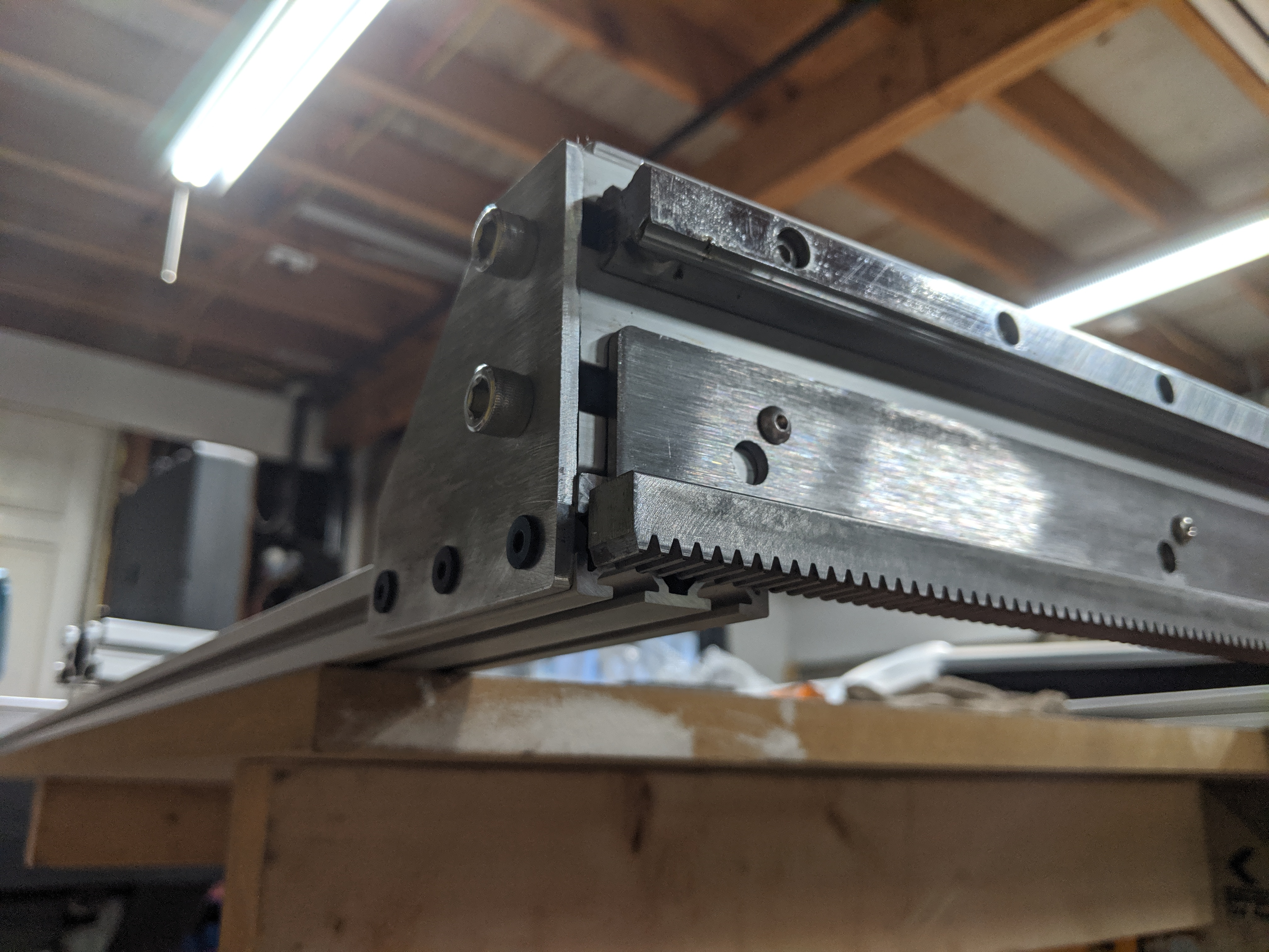
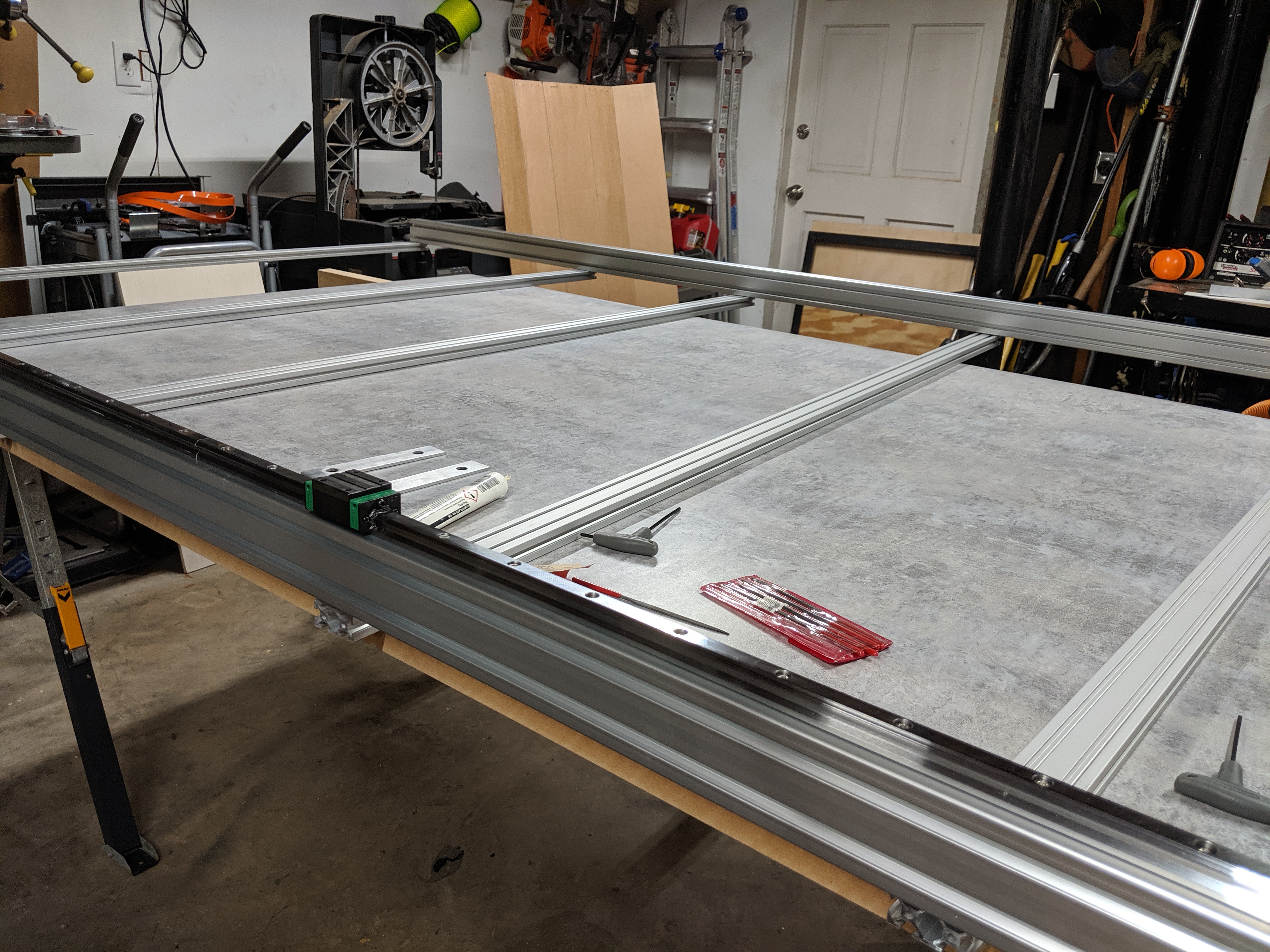
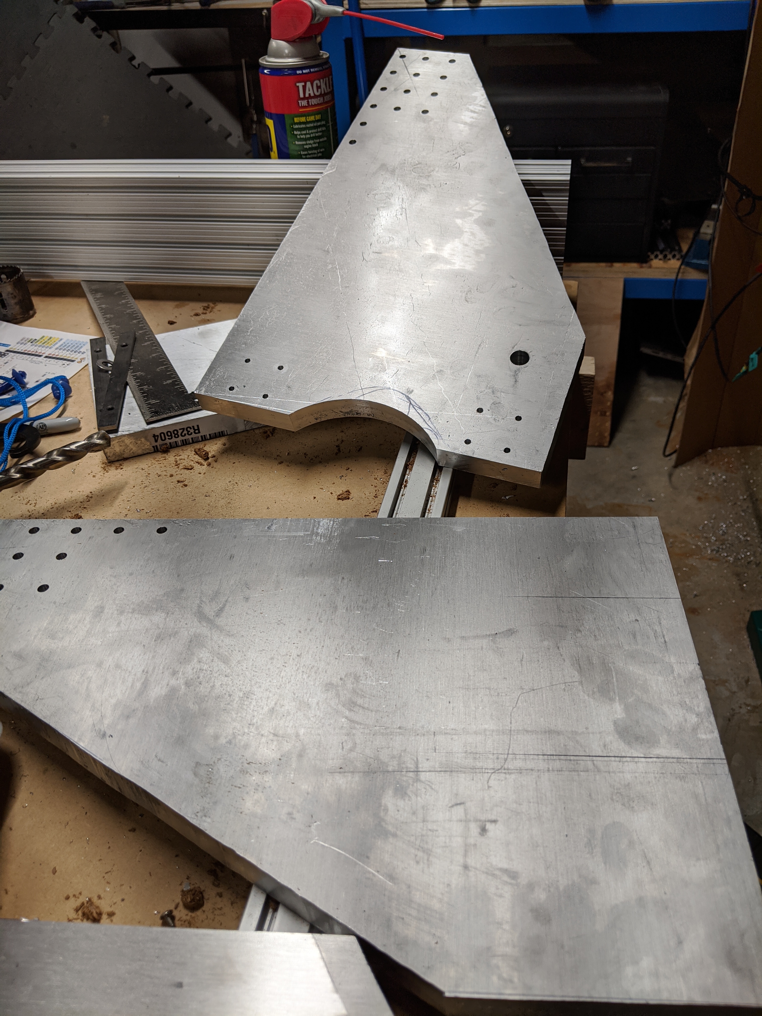
The frame structure used thick aluminum tube for rigidity. Gantry plates were waterjet-cut to rough dimensions, then finish-machined on the G0704. I specified linear rails throughout for smooth, accurate motion.
Scale introduced challenges absent from smaller machines. The assembled unit would not fit through standard doorways, requiring in-place assembly in my workshop. I built a torsion box table as the machine’s base, keeping the surface flat across the entire footprint. With the machine’s significant mass, the leveling feet needed to be substantial and properly positioned.
Machining the Components#
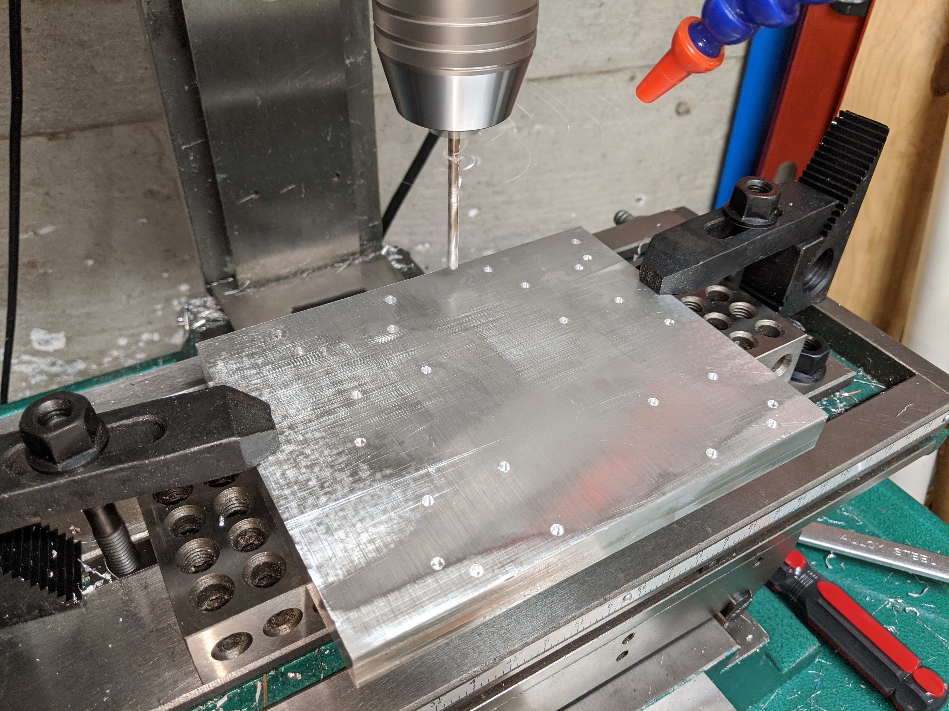
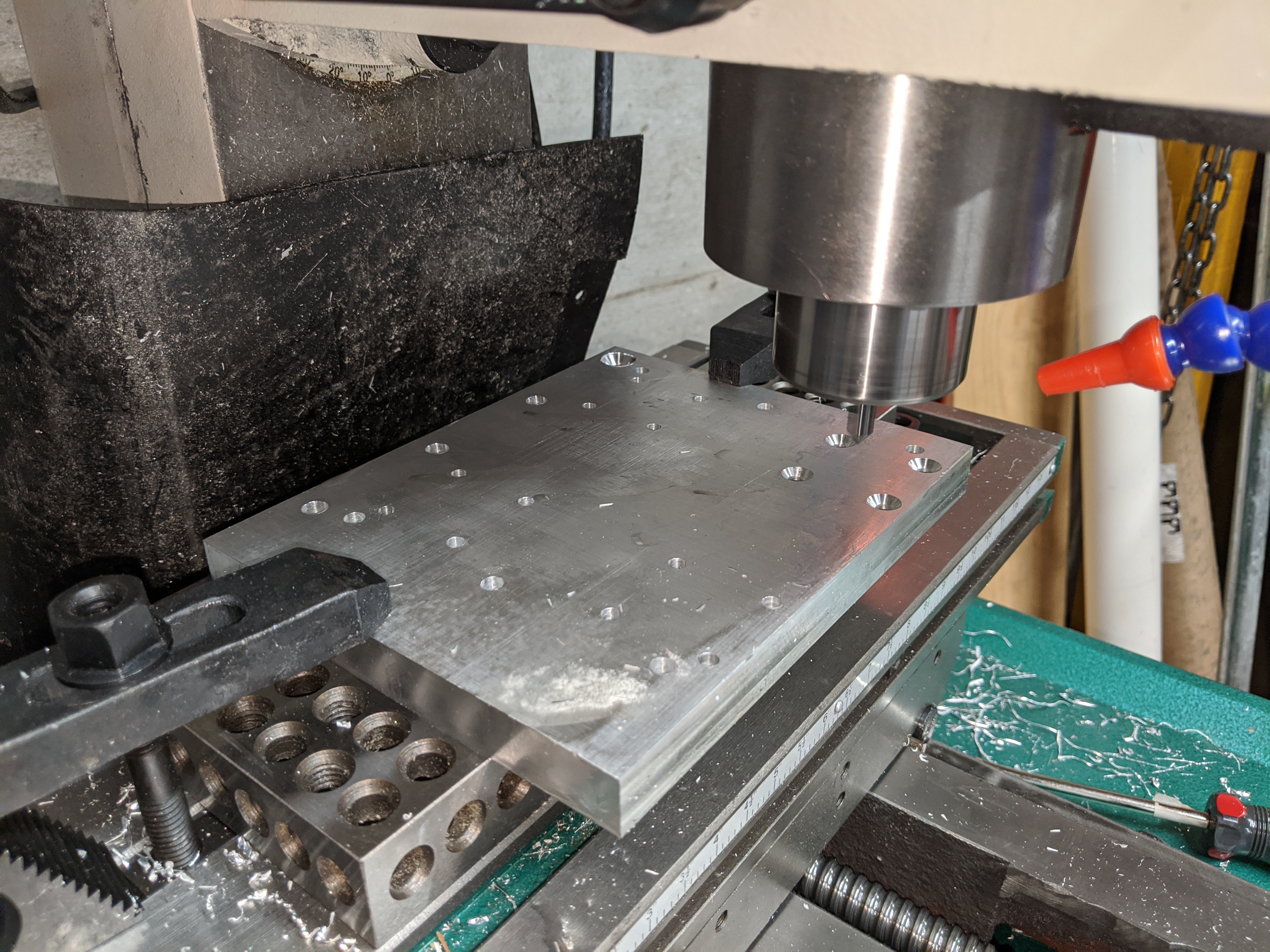
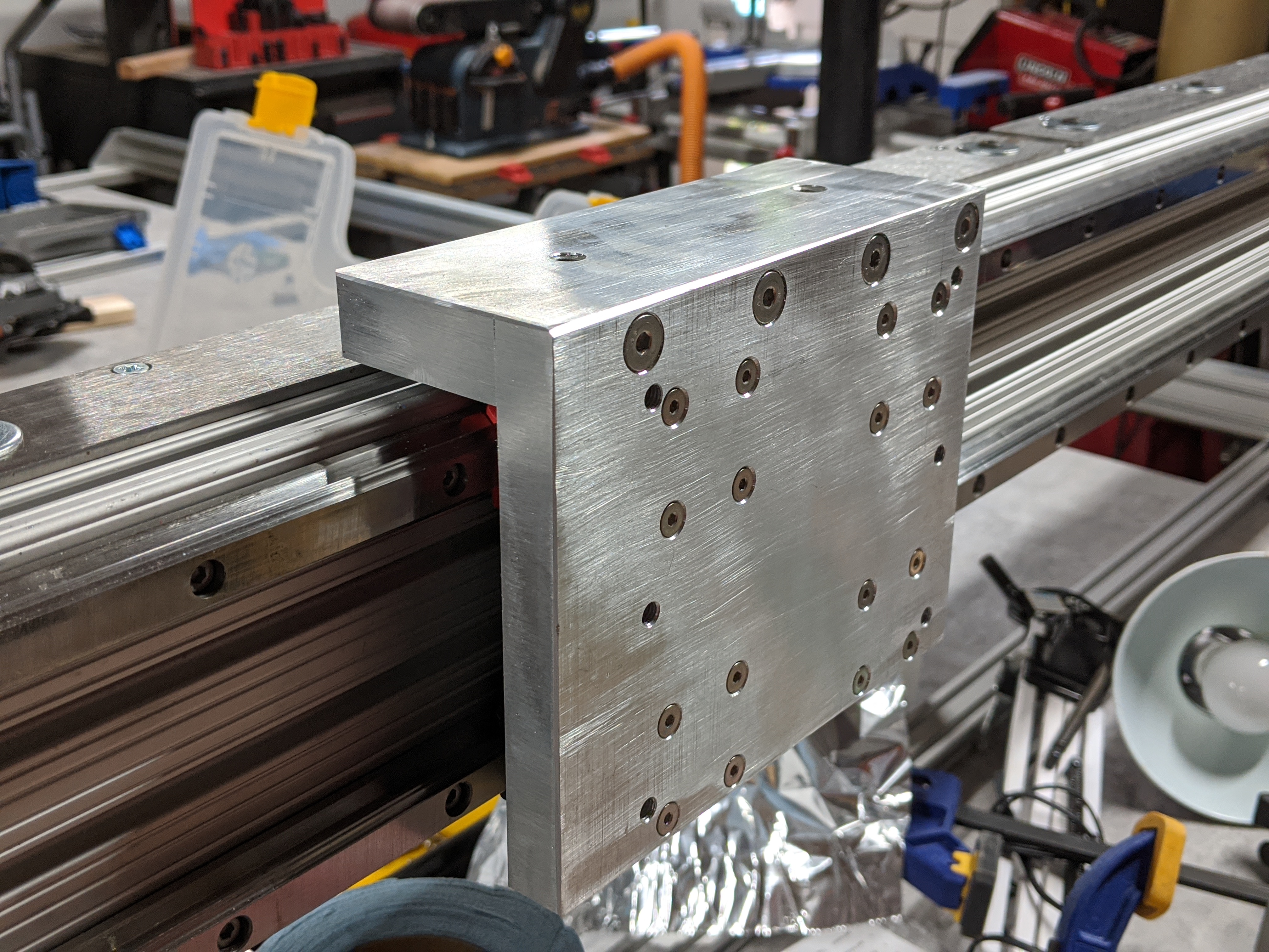
Every gantry plate underwent multiple operations on the G0704: facing both sides for parallelism, drilling mounting holes, tapping threads, boring bearing pockets, and profiling edges. Each plate required weeks of machining time and multiple setups. I designed all components to fit within the G0704’s working envelope, breaking larger assemblies into bolt-together sections when necessary. The precision achieved during machining paid dividends during assembly, and components fit together with minimal adjustment.
Milling the Z-axis gantry plate on the G0704
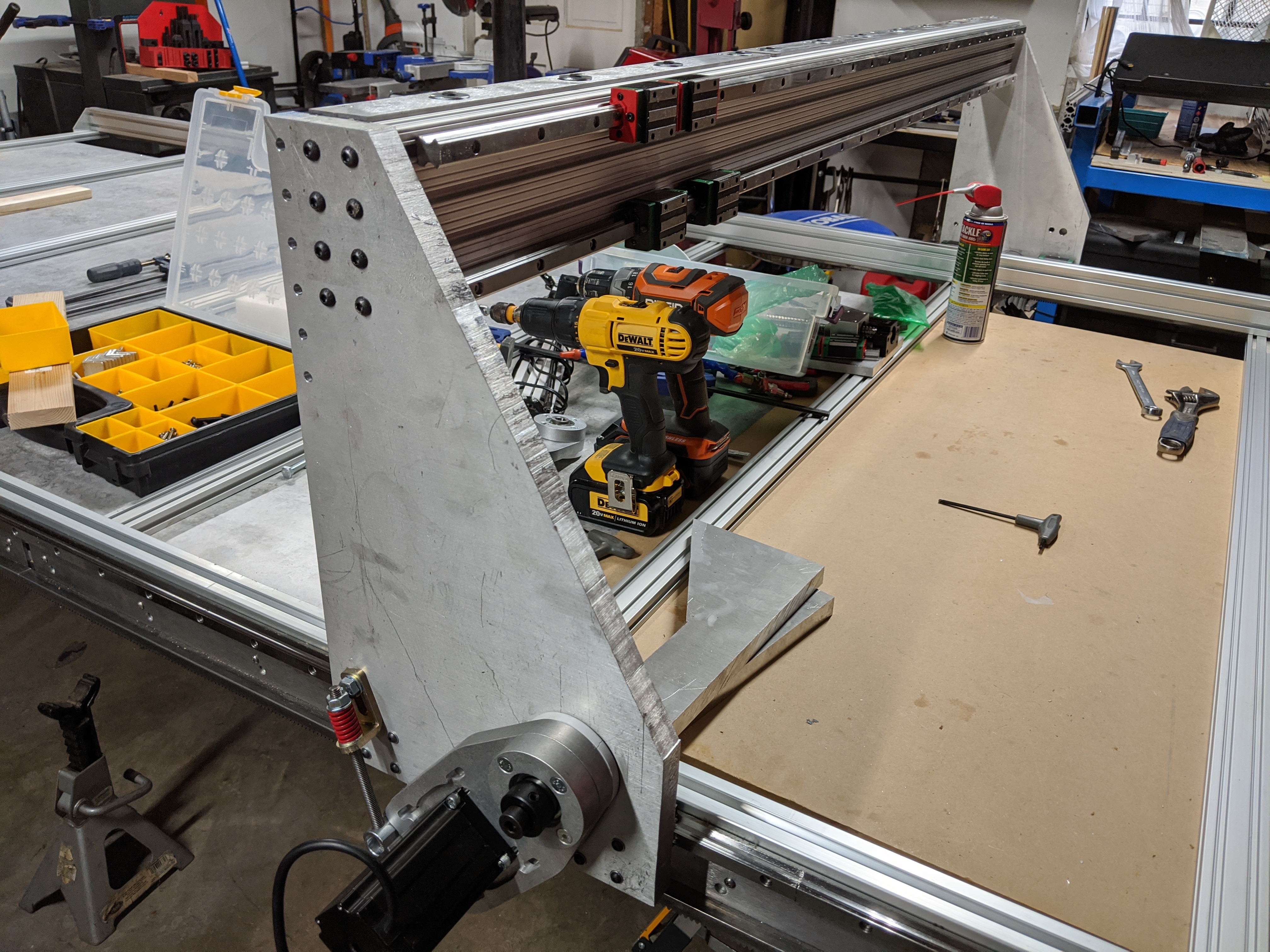
Frame assembly involved connecting corner posts with long beams and adding cross-members for torsional rigidity. The gantry plates connected via a cross-beam with linear rails mounted to their working surfaces. Y-axis bearing blocks allowed the entire gantry assembly to traverse the full length of the machine.
Alignment at Scale#
Alignment techniques that worked on smaller machines proved inadequate at this scale. I used a laser level to establish reference planes. Linear rails had to stay nearly parallel across their entire length. I measured frame diagonals repeatedly to keep the frame square.
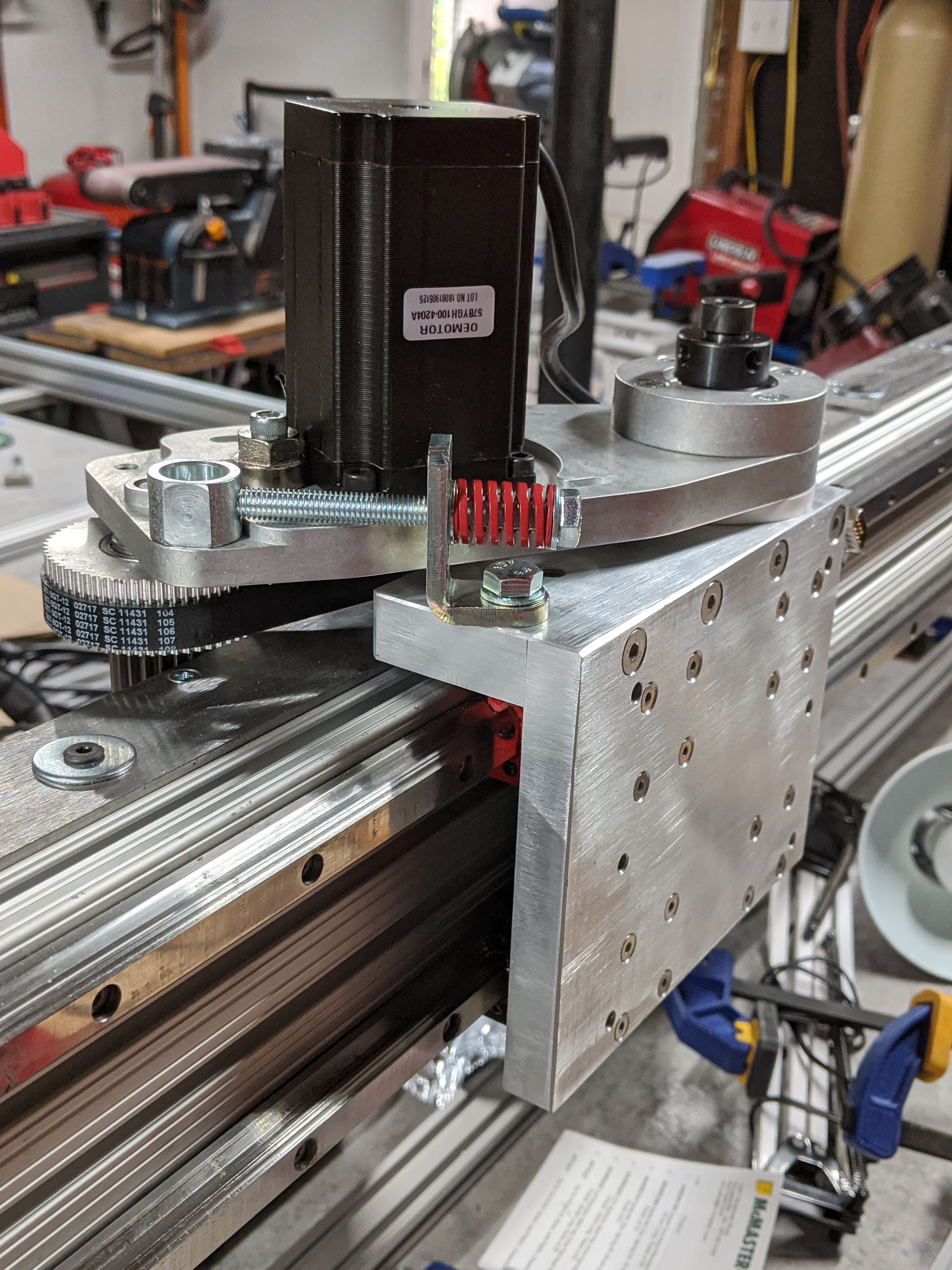
Steel gear racks mounted along both sides of the machine. Setting proper mesh depth between pinion gears and racks demanded precision, so I used feeler gauges to dial in a tight fit. The Y-axis employed dual motors software-synchronized to prevent racking forces from misaligning the gantry.
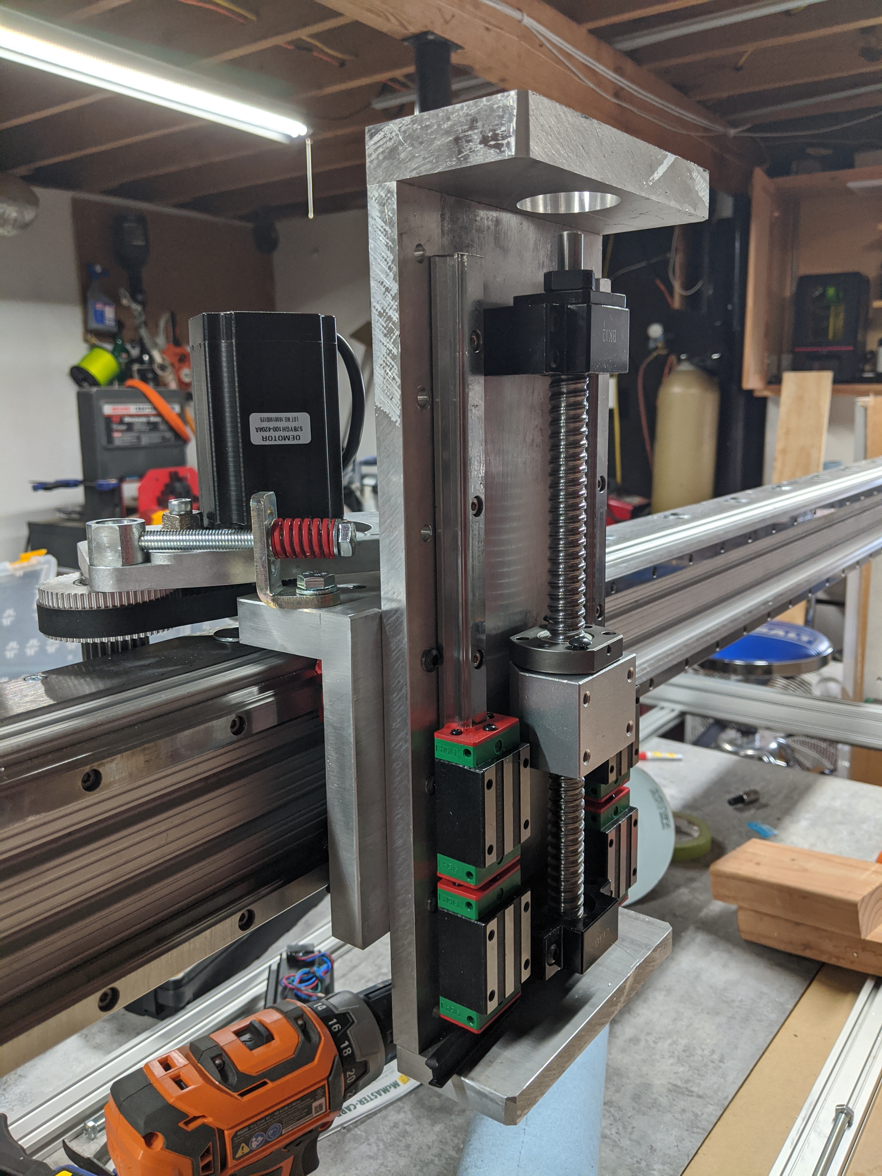
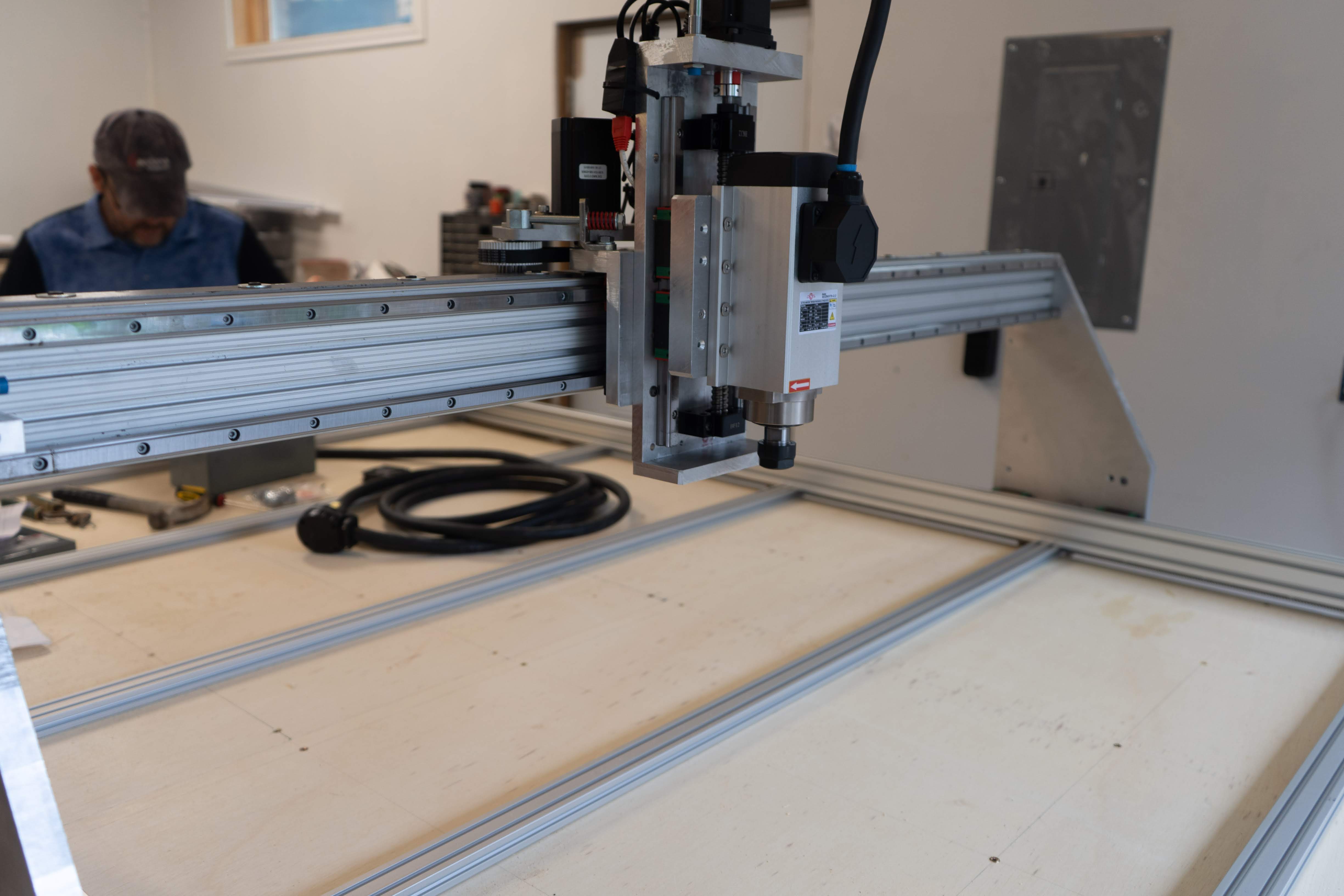
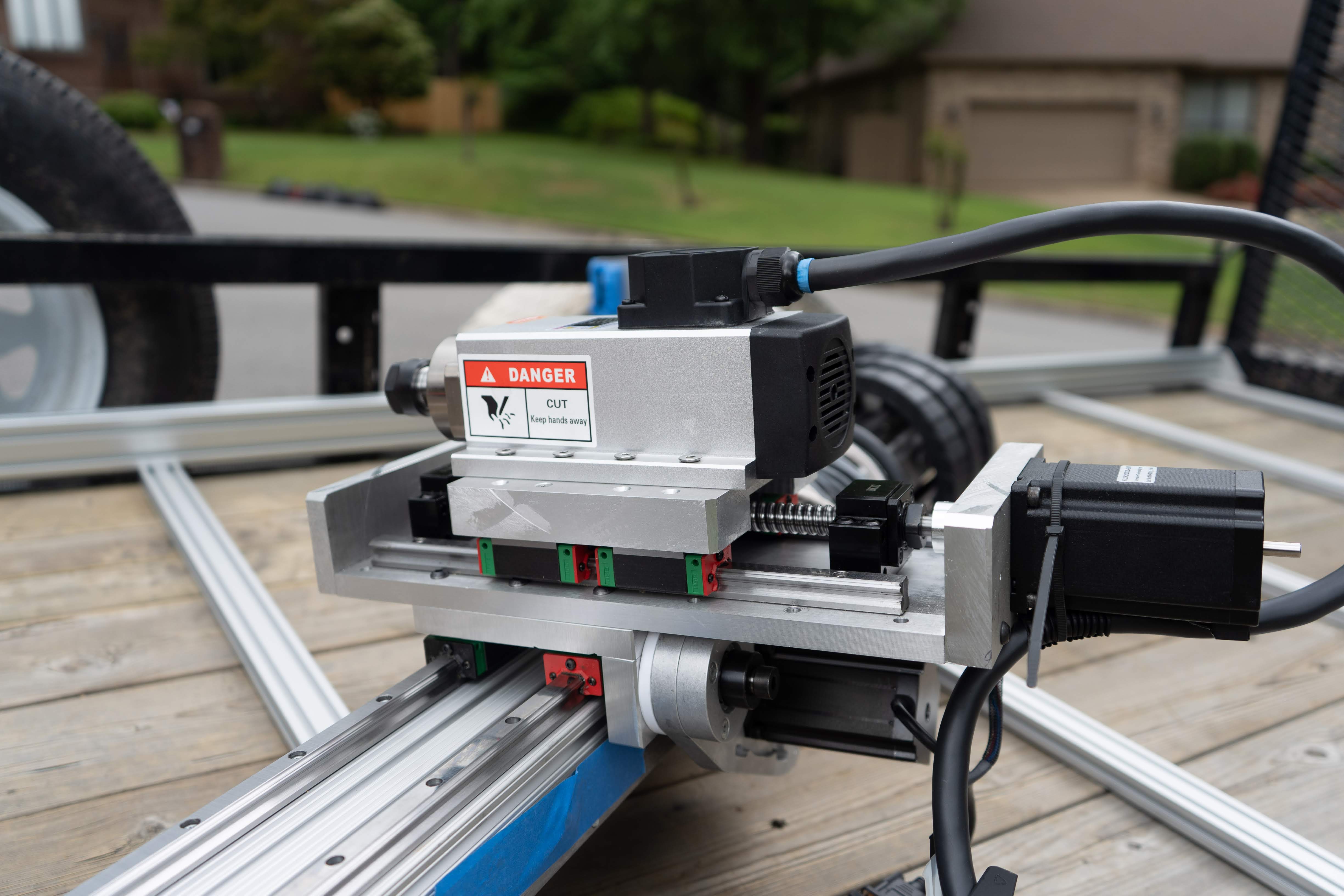
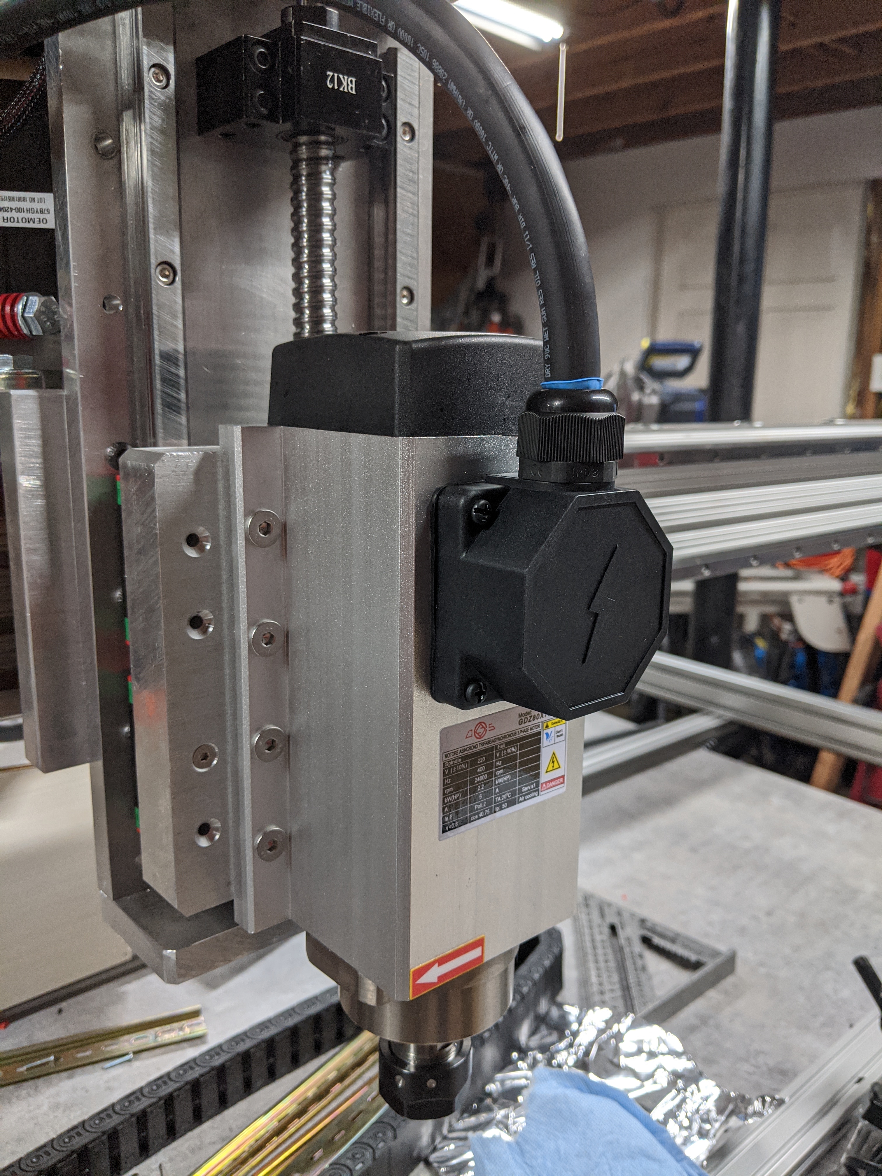
The Z-axis used a ballscrew identical to the one in the G0704 conversion. I mounted a water-cooled spindle with an ER20 collet range. While overkill for cutting wood and plastic sheet goods, this spindle power proved necessary for aluminum work.
Electronics and Control#
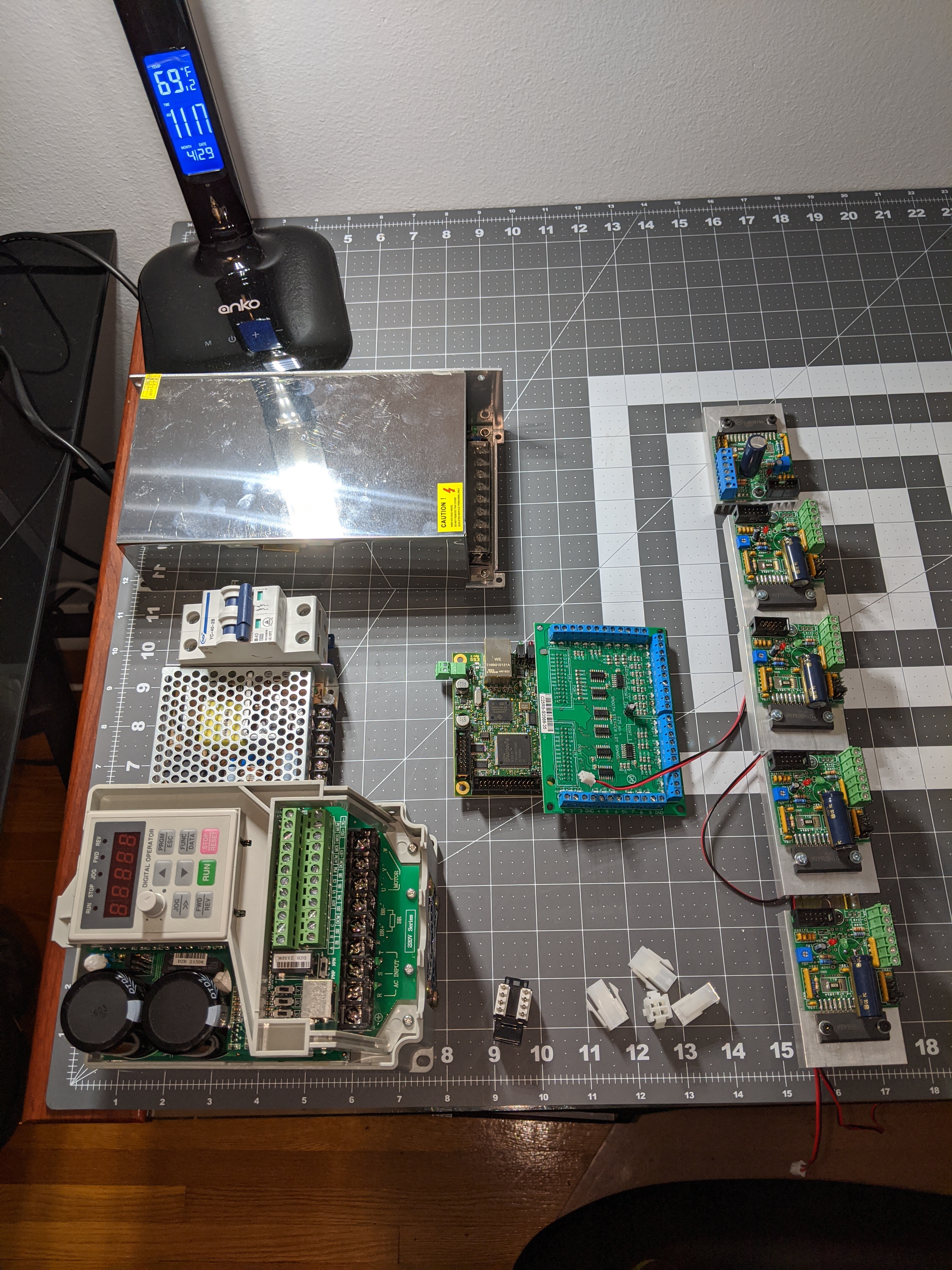
The machine used digital stepper drivers paired with high-torque NEMA 34 motors. I eventually swapped the drivers for higher-power units with integrated heatsinks to keep them stable during long carving jobs. An Ethernet SmoothStepper running Mach3 provided machine control. Separate power supplies handled the stepper motors and the variable frequency drive controlling the spindle.
Cable chains on all three axes protected wiring from damage during motion. I used shielded cables throughout and implemented proper strain relief at every connection point.
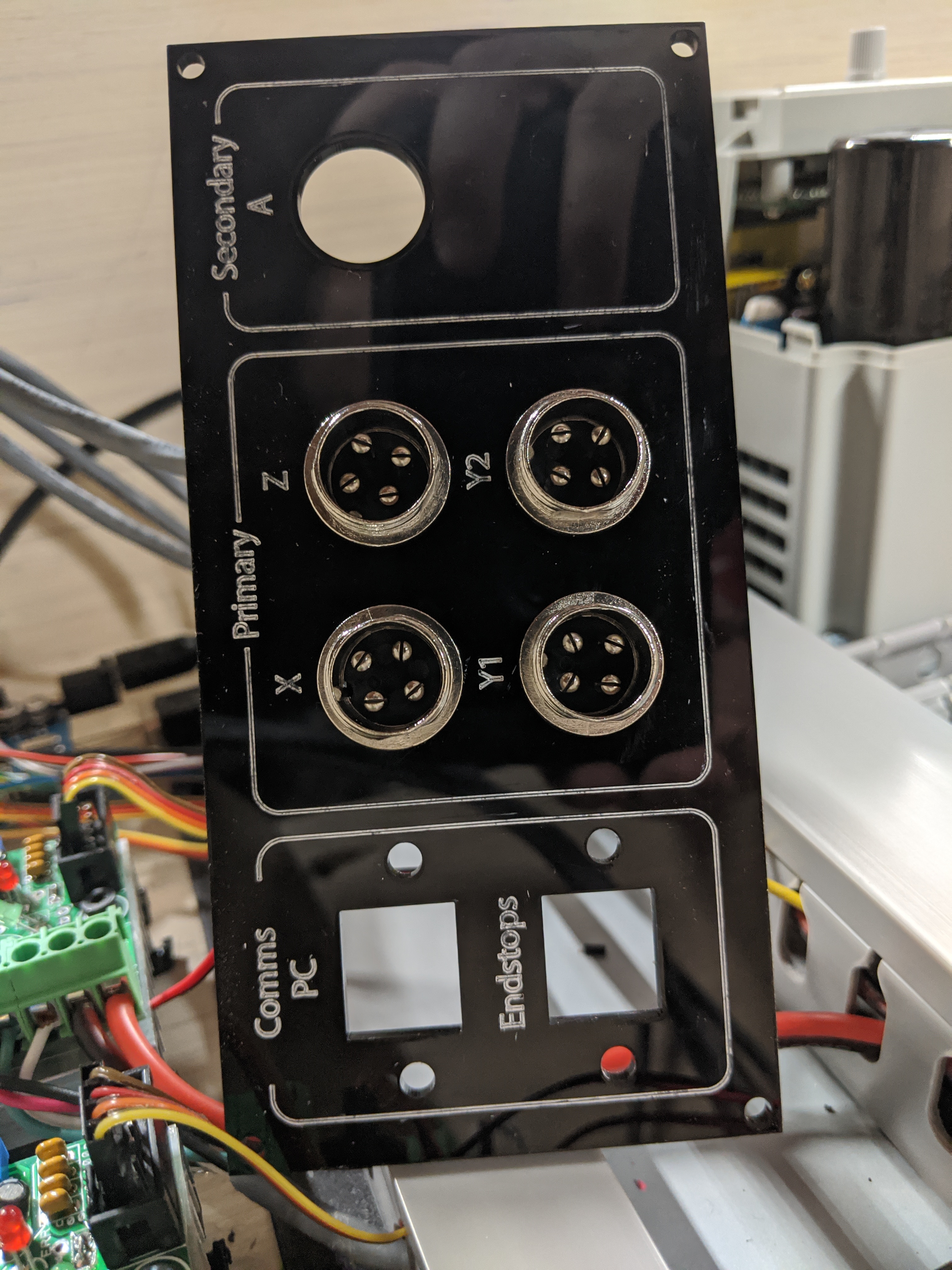
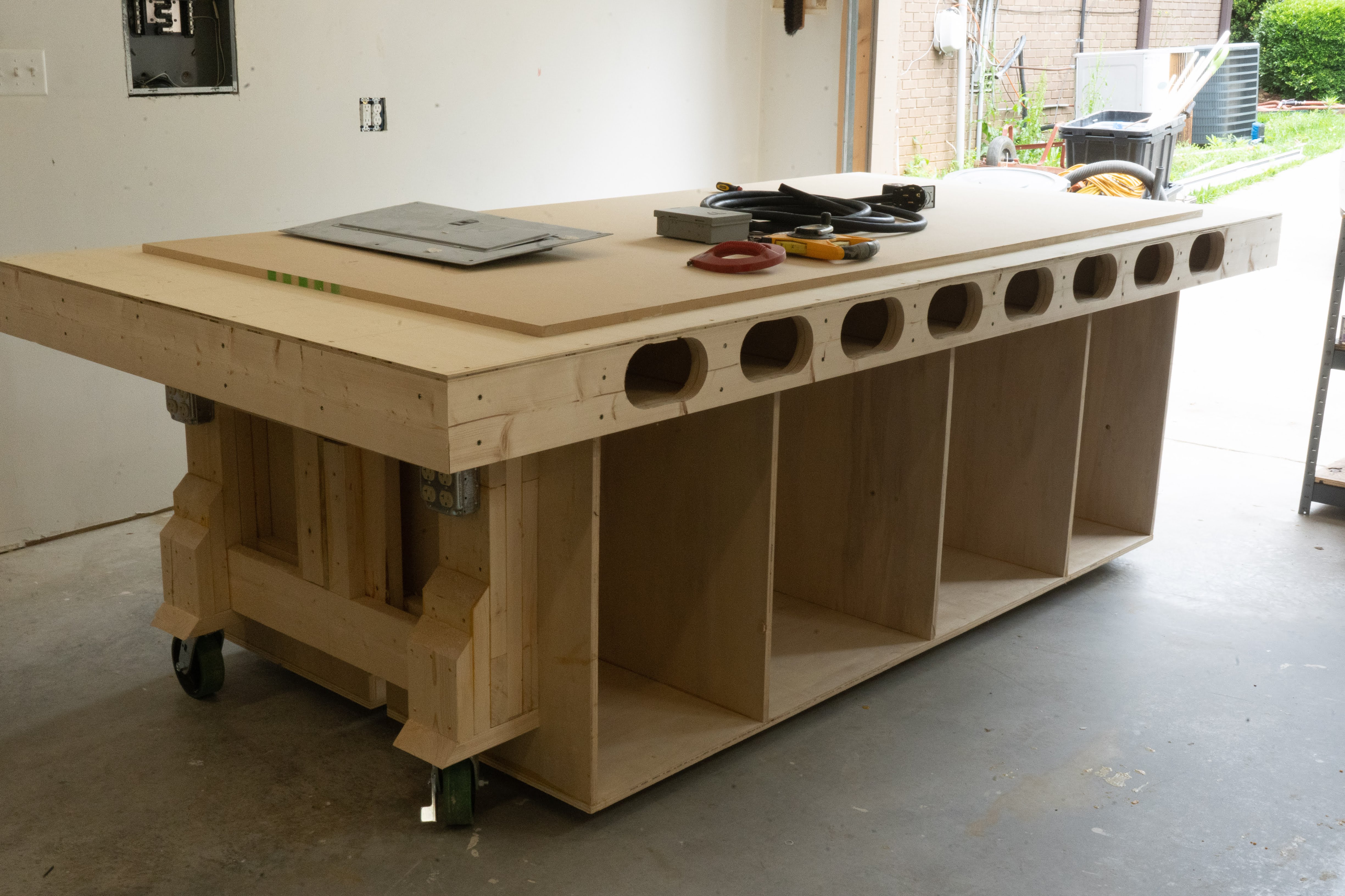
A machine of this size still needs occasional repositioning. I designed a custom wheeled cart with locking casters, incorporated storage underneath for tooling and accessories, and integrated electrical distribution panels for convenient power management.
Calibration and Performance#
Calibration began with theoretical calculations based on rack pitch and motor steps, but actual test cuts and measurements refined the values. I dialed in accuracy across the full travel range, verifying it by cutting a large square and comparing the diagonals.
The machine handled various materials effectively: MDF, plywood, thick aluminum plate, and HDPE all cut cleanly with appropriate tooling and parameters.
Key characteristics: 5×10 working envelope, rack-and-pinion drive on X and Y axes, a ballscrew-driven Z axis, fast rapids, and consistent positioning once tuned.
Results and Reflection#
The machine exceeded my initial expectations. Full sheet processing eliminated material waste from edge trimming. Aluminum milling capability enabled fabrication of structural components impossible on the 3D printer or smaller CNC machines. The reliability permitted unattended operation for extended production runs. Once properly calibrated and tuned, the machine required minimal ongoing maintenance.
The three months invested in CAD design prevented countless assembly problems. The hybrid approach, combining a commercial drive system with a custom frame, proved wise. Attempting to manufacture rack-and-pinion components from scratch would have been extremely challenging.
This machine was only possible because of the tool progression that preceded it. The McWire RepStrap printed parts for the Mendel. The Mendel printed components for a larger 3D printer. That printer manufactured mounting brackets for the OX CNC router. The OX machined parts for the G0704 conversion. The G0704 machined every gantry plate and mounting bracket for this build. Now this large-format router produces components impossible to fabricate on any previous machine.
The full-sheet working envelope accommodates most projects I encounter. The spindle power handles demanding materials. The structural rigidity maintains accuracy under load. This machine represents what I should have built years earlier, but I lacked the experience and supporting equipment to execute successfully.
Editor’s Note (2025): Large-format CNC routers have become more accessible with companies like AVID, ShopBot, and Laguna offering complete systems. However, custom builds like this still offer advantages in cost, customization, and learning. Modern builds increasingly use servo motors instead of steppers for better high-speed performance. Closed-loop systems have become more affordable, offering stepper simplicity with servo reliability. The 3D-printed-to-aluminum motor mount progression exemplifies the bootstrap manufacturing philosophy by using the machine under development to iteratively improve itself. Regardless of specific component choices, the fundamentals remain: rigid frame, precise linear motion, adequate spindle power, and proper alignment. This build demonstrates that with patience, proper planning, and incremental tool development, truly professional-grade equipment is achievable in a home workshop.