I built my McWire RepStrap in 2008, a custom cartesian robot designed to eventually print parts for a proper RepRap 3D printer. The name came from its wire-based construction and modular design philosophy. From that starting point, I built two complete electronics upgrades, at least three different extruder designs, and made numerous improvements to the mechanical system.
What is a RepStrap?#
A RepStrap is a bootstrapping machine, a 3D printer or CNC platform built from non-printed parts that can eventually manufacture components for a “real” RepRap (Replicating Rapid Prototyper). The goal is self-replication: use readily available materials like threaded rod, plywood, and hardware store components to build a machine capable of printing the specialized plastic parts needed for a proper RepRap Mendel.
The McWire Design#
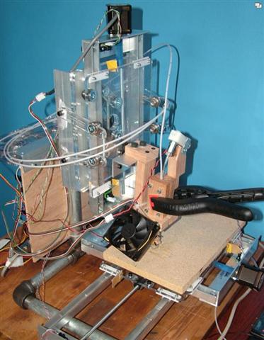
The McWire used a gantry-style cartesian coordinate system with three axes of motion. Unlike many early RepRap designs that used printed parts, the entire frame was constructed from threaded rod for linear motion rails, basic lumber and plywood for the frame, standard hardware store components, salvaged stepper motors from various sources, and custom electronics assemblies.
The machine earned its name from the extensive use of wire and cable management required to coordinate all the moving parts. While not elegant, it proved to be a capable platform for learning the fundamentals of 3D printing, CNC control systems, and thermoplastic extrusion.
Early Electronics: Generation 2#
My initial electronics setup used Generation 2 RepRap boards, massive compared to modern controllers. These featured through-hole components and required extensive wiring. The system included a main motherboard for coordinating all motion, separate stepper motor driver boards, an extruder controller for managing the hotend, and an ATX computer power supply for the 12V rail.
Getting these boards to communicate reliably was a challenge. The firmware was still maturing, and troubleshooting required a solid understanding of both electronics and embedded programming.
The Generation 3 Electronics Revolution#
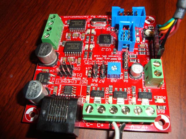
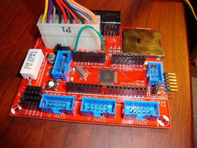
The Generation 3 electronics represented a massive leap forward in technology. Instead of through-hole components, these boards used surface-mount technology (SMT), dramatically reducing the size and complexity of the system.
To assemble SMT boards, I applied a small dab of solder paste to each pad, carefully placed components with tweezers, then heated the entire board on a hotplate. Once the board reached the solder paste melting point, surface tension pulled each component perfectly into place. It was almost magical to watch. The process was actually easier and faster than traditional through-hole soldering once I developed the technique.
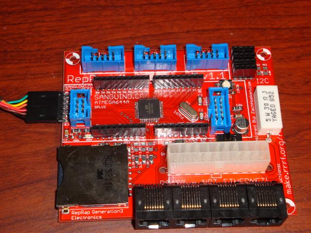
The main control board featured a Sanguino microcontroller and used an ATX computer power supply for clean, stable power. One challenge: the RepRap firmware controlled the power supply’s on/off state. To test the motherboard independently, I had to jump the power supply pin to ground, effectively forcing it to stay on regardless of what the microcontroller wanted.
Getting the first stepper motor to respond was thrilling. After weeks of assembly and troubleshooting, hearing that distinctive stepper motor hum meant all the work was paying off.
Mounting the Gen3 Electronics to McWire#
With the electronics tested and working on the bench, it was time to mount everything to the McWire frame.
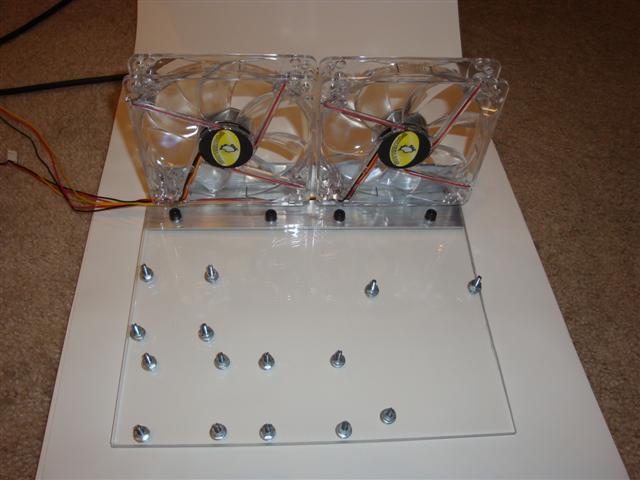
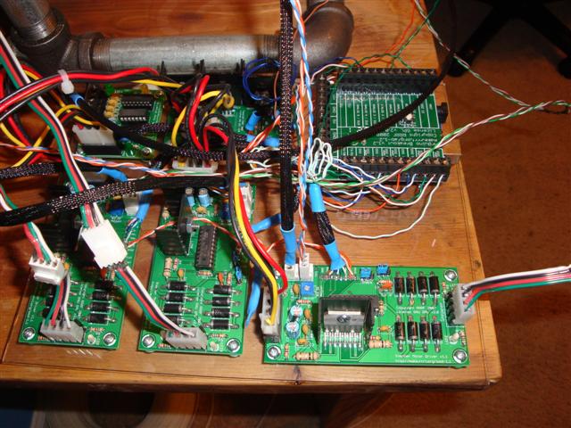
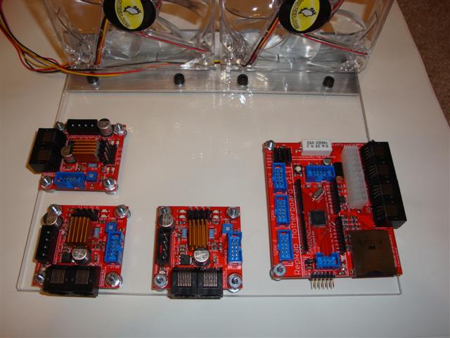
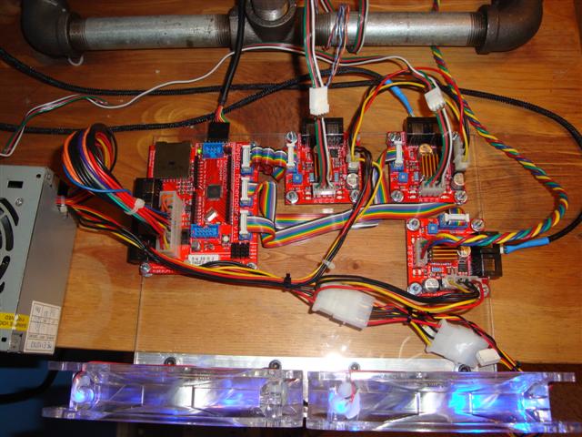
I used acrylic sheet as the base plate. The fans were mounted to aluminum angle stock for cooling the stepper drivers. To determine hole placement, I arranged all four boards on the acrylic and marked drill locations with a marker.
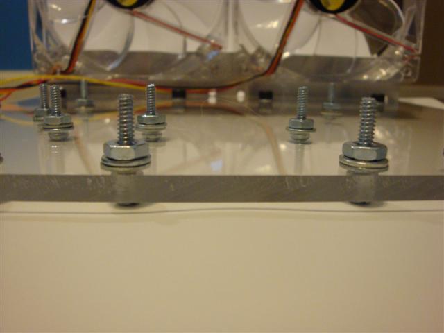
The boards needed spacing from the base to allow airflow and prevent shorts. I used washers and nuts as spacers to lift the boards approximately half an inch off the base.
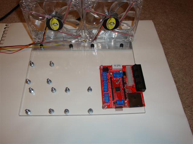
The motherboard went on first. I had to drill out the corner holes slightly to account for less-than-perfect placement of the mounting studs. This extra clearance also made it easier to adjust the board’s position during installation.
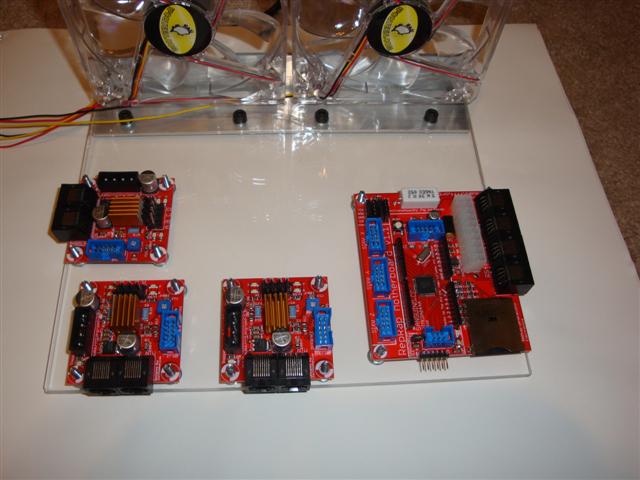
Before final assembly, I test-fit all boards to make sure everything lined up. I also added heatsinks to the stepper driver chips. While this might not have been strictly necessary, the drivers were getting uncomfortably hot during testing.
With the motherboard secured, the stepper controllers went on next. Installing the ribbon cables in a neat fashion proved nearly impossible because the cables required extensive folding and careful routing to fit under adjacent boards without creating strain on the connectors.
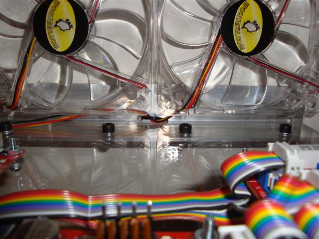
Zip ties kept cables organized and prevented them from interfering with moving parts.
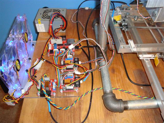
Once assembled, I mounted the electronics plate to the McWire frame and began testing with ReplicatorG, the primary host software for RepRap machines at the time.
Initial testing revealed several issues. Testing X-axis motion moved both X and Y axes. The solution was reflashing the motherboard firmware. Axis motion scale was incorrect, so I updated the ReplicatorG machine definition with correct steps-per-millimeter values. X and Y axis movement was jerky, which I fixed by adjusting feedrate settings in the ReplicatorG machine configuration. Optical endstops weren’t triggering, so I changed the endstop mode in motherboard firmware to use version 1.0 style detection.
After these adjustments, the McWire’s motion system worked smoothly. The next challenge would be getting reliable extrusion, a topic that would consume months of experimentation and iteration.
What’s Next#
With the frame built and electronics operational, the focus shifted to the most challenging component of any 3D printer: the extruder. Creating a mechanism that could reliably melt and deposit plastic filament would prove far more difficult than anticipated.
The next article in this series covers the evolution of extruder designs, from the initial nichrome-heated barrels to the more reliable resistor-based heater blocks that eventually produced consistent results.
Editor’s Note (2025): This article combines several posts from April-May 2009 documenting the early McWire build. The language has been updated for clarity and readability, but the technical content reflects the actual state of hobby 3D printing in 2009. The challenges described, such as getting Generation 3 electronics working, dealing with unreliable firmware, and navigating the general DIY nature of the hobby, were typical of the early RepRap community.