Building a reliable extruder proved to be the most challenging aspect of the entire RepRap project. Over two years of experimentation, I went through multiple complete redesigns before achieving consistent extrusion. This article documents that journey, from early nichrome-heated failures to working pinch-wheel designs and eventually the resistor heater blocks that finally produced reliable results.
The Extruder 2.0: Nichrome and Furnace Cement#
My first serious attempt used the RepRap community’s Mk 2 extruder design. The heater consisted of nichrome resistance wire wrapped around a brass barrel, with the entire assembly encased in high-temperature furnace cement. The cement held the nichrome wire in position, secured the thermistor against the barrel, provided thermal insulation, and protected the heating element from damage.
I found furnace cement at the hardware store rated to 1000°F. While not the highest temperature rating available, it proved sufficient for melting both ABS and PLA. Fresh from the tube, the cement was black and gritty, but it hardened to approximately the consistency of silicone rubber.
The curing process was dramatic. I heated the assembly to about 240°F for roughly an hour. During the first fifteen minutes, the cement hissed and bubbled like a volcano, with very hot steam shooting from cracks and holes. After twenty minutes, the activity subsided and the cement hardened to a rock-like state.
After curing, the surface showed a cratered texture with white ash deposits. While this approach worked, it had significant drawbacks: difficult to service or repair once assembled, inconsistent temperature readings due to thermistor position variation, fragile construction that could crack if dropped, and time-consuming assembly.
Proof of Concept: Gear-Driven Design#
After the nichrome approach’s mixed results, I designed a new extruder using parts I already had on hand. The goal was to eliminate printed components entirely, using only materials available at hardware stores. The design featured an acrylic or aluminum back plate, gears salvaged from broken drills for increased torque, steel guide tubes for the filament path, spare skate bearings for the idler wheel, and the existing heater barrel assembly.
After discussing the design on the RepRap forums, I revised the gear ratios to provide better mechanical advantage. While I was working on this, someone else in the community independently built a similar design using a stepper motor instead of a gear motor, which validated that the concept was sound.
The Pinch-Wheel Stepper Extruder#
This version became my first truly functional extruder. The motor mount was cut from acrylic sheet with holes drilled to match the NEMA 17 stepper motor mounting pattern. A second hole held the pressure wheel, a skate bearing that would press the filament against the drive gear.
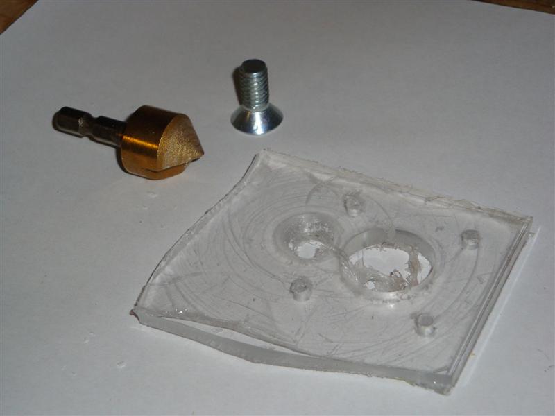
To position the idler wheel hole accurately, I mounted the motor with the drive wheel installed, placed a piece of filament between the drive wheel and bearing, then marked the bearing’s center with a marker. The hole was countersunk on the motor side so the mounting bolt head wouldn’t interfere.
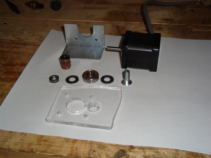
The assembly used standard hardware: a countersunk bolt, washers, a nut, a skate bearing, acrylic sheet, aluminum angle stock, a NEMA 17 stepper motor, copper tube for the filament guide, and the heater barrel assembly from previous attempts.
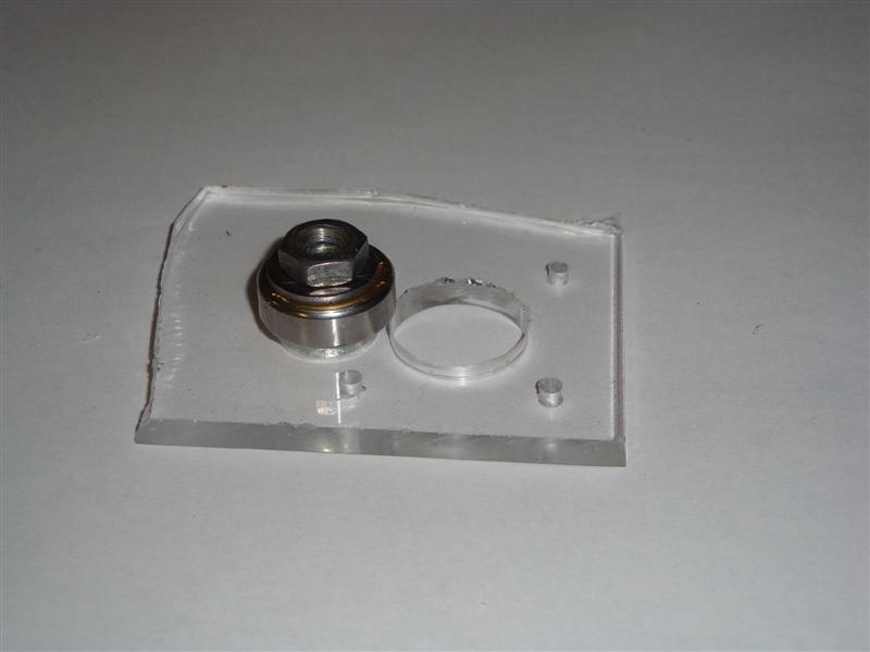
The skate bearing assembly mounted flush on the back side, allowing the stepper motor to sit flat against the mounting plate.
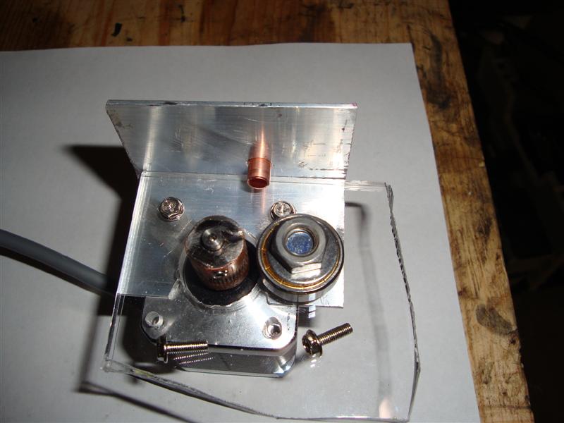
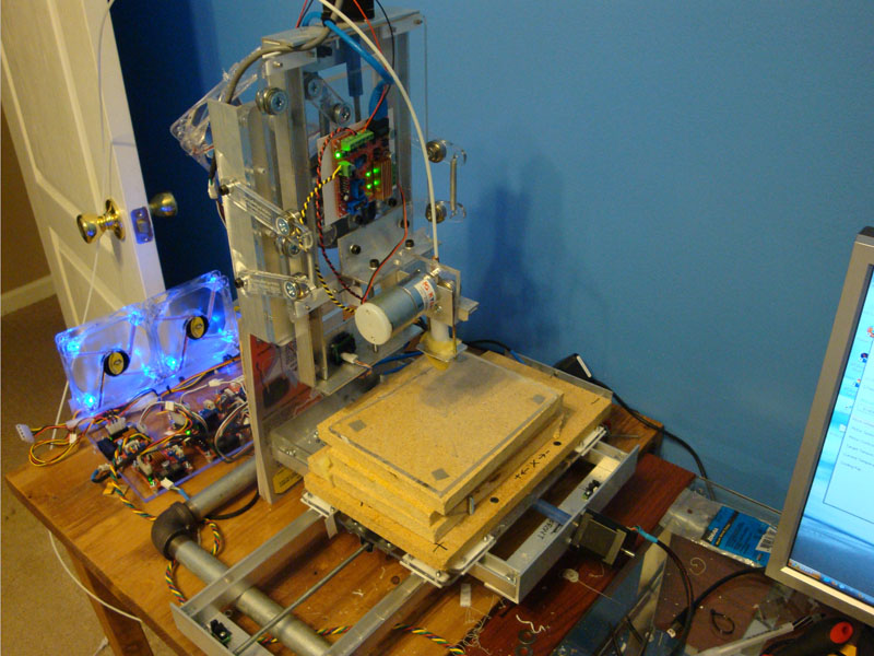
With most components in place, I could test the mechanical grip. Aluminum angle stock provided the mounting bracket to attach the entire assembly to the McWire’s Z-axis.
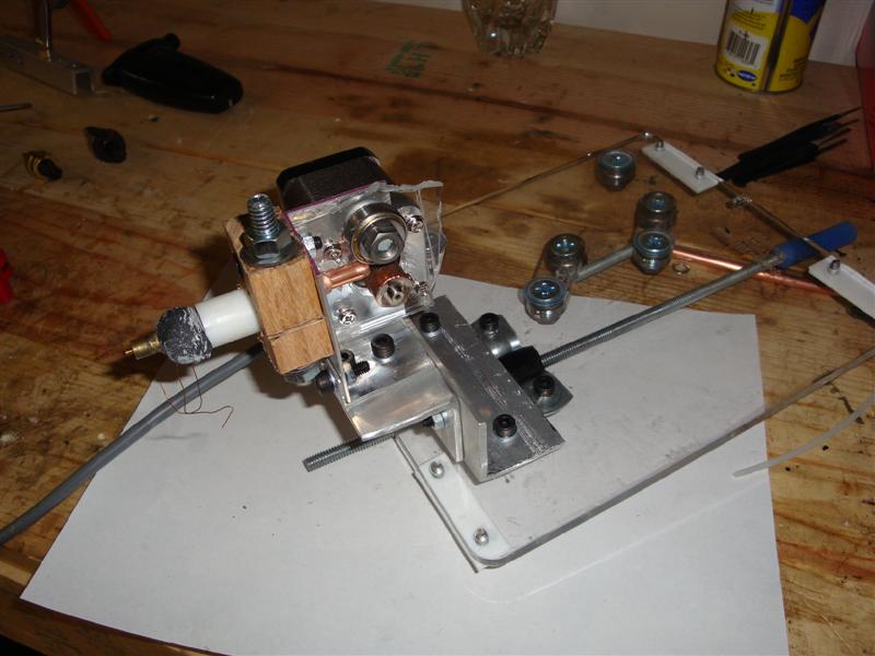
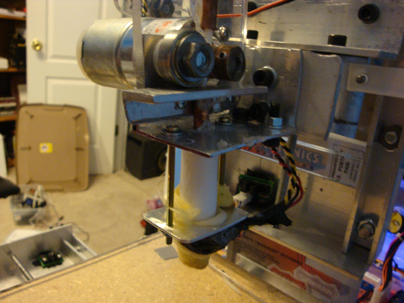
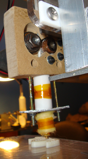
The completed extruder attached to the Z-axis. The copper tube was hot-glued in place as a filament guide, and a piece of oak clamped the nozzle assembly to the motor mount. For electrical connections, I twisted wire onto each thermistor lead and heater coil connection, covered with heat shrink tubing. A layer of fire cement over the heat shrink provided additional strain relief and protection.
During initial testing, the assembly reached 220°C in about two minutes. The next challenge was getting the extruder controller to drive a stepper motor instead of the default gear motor it was designed for.
First Successful Extrusion#
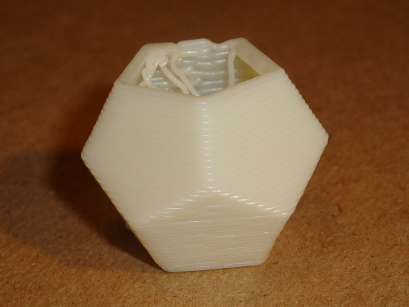
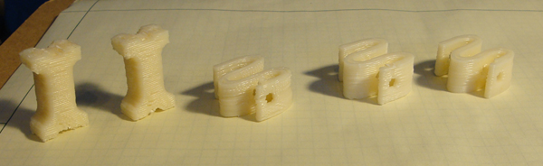
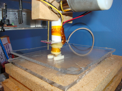
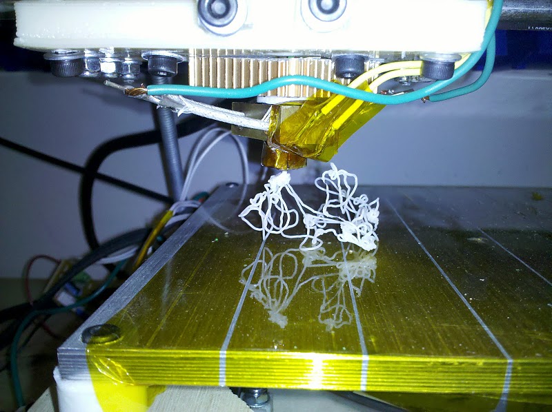
After over two years of work, I finally extruded a complete object. The settings needed tweaking for quality, but seeing that first finished piece was incredible.
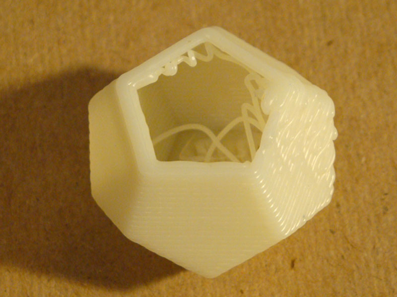
The layer transitions showed issues that required Skeinforge adjustments. Additionally, my 0.5mm nozzle created lower resolution prints but significantly faster build times, and this test object took only 15 minutes from start to finish.
The MDF Rebuild: Improved Build Quality#
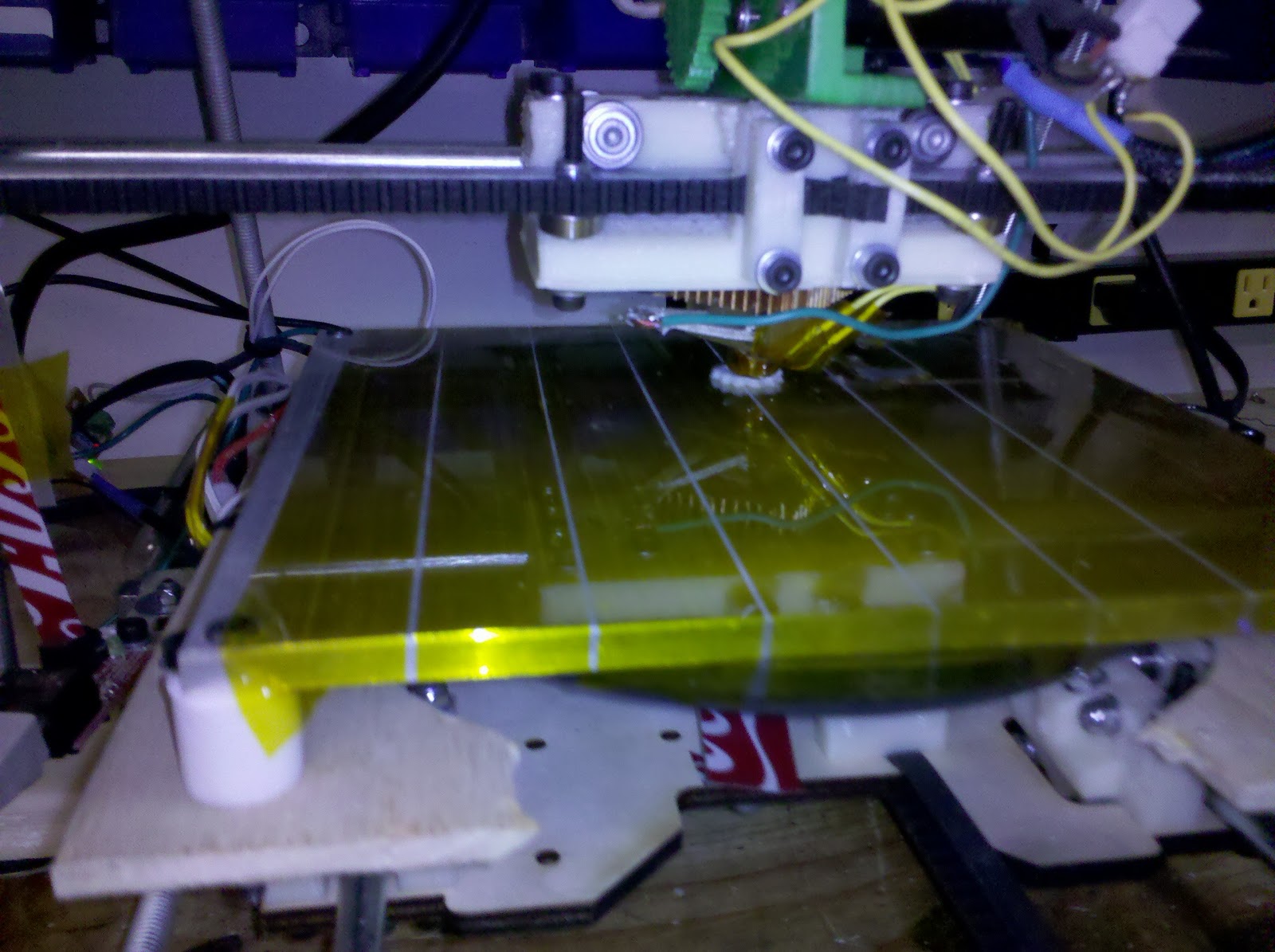
After building two more iterations, I developed an extruder construction technique using medium-density fiberboard (MDF) with a single aluminum angle bracket for mounting. Using just a hand drill and calipers to measure hole placement, I could assemble a working extruder in about 30 minutes. This design worked far better than anything I’d built previously, producing parts as fast as Skeinforge could process them.
I ran this setup at approximately 225°C with a layer height of 0.7mm, which provided a good balance between speed and quality for structural parts.
The Double Resistor Heater Block#
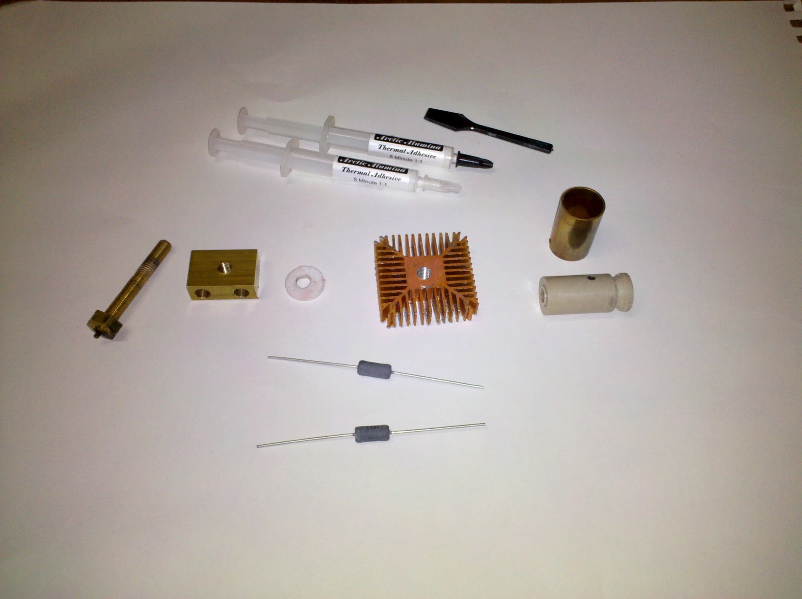
A single resistor heater couldn’t provide enough power for consistent extrusion at higher speeds. Inspired by Makerbot’s designs, I machined a double resistor heater block from solid brass to maximize thermal mass and heat distribution.
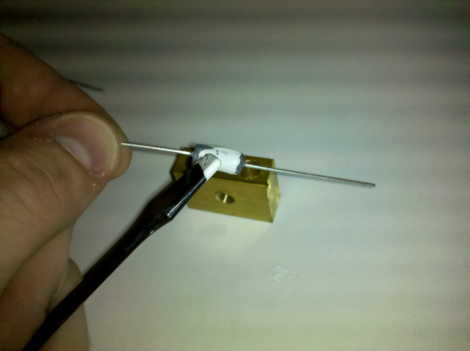
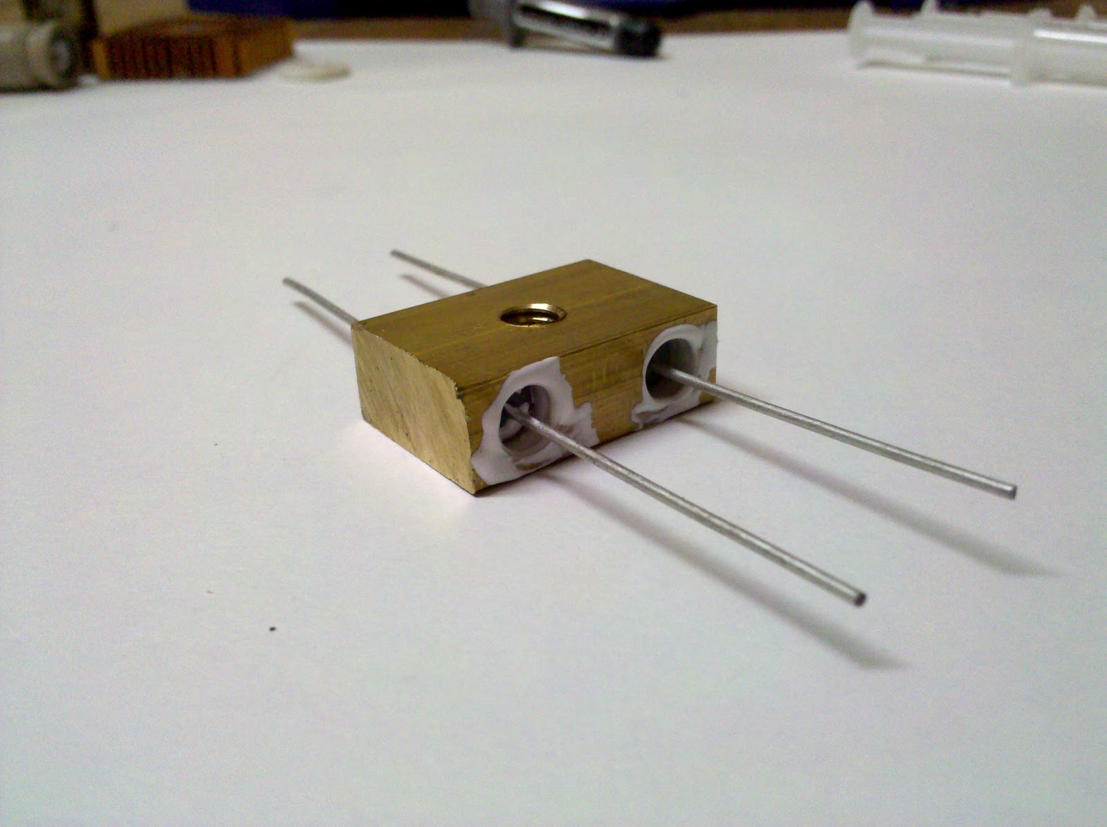
I mixed heatsink epoxy and coated the resistors thoroughly before inserting them into the heater block. This permanently bonded them in place, so precise positioning was critical. After about five minutes, the epoxy set enough to handle.
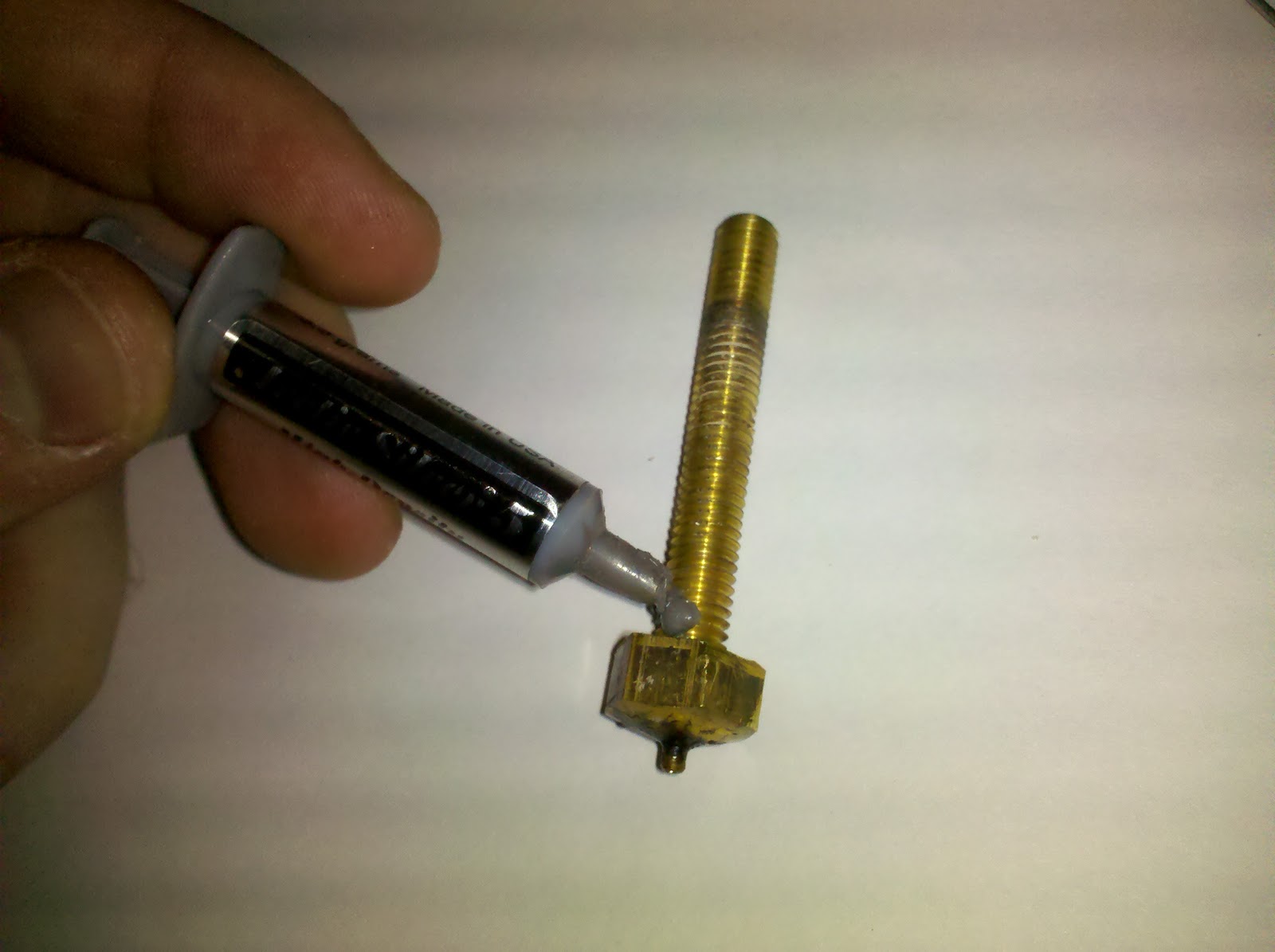
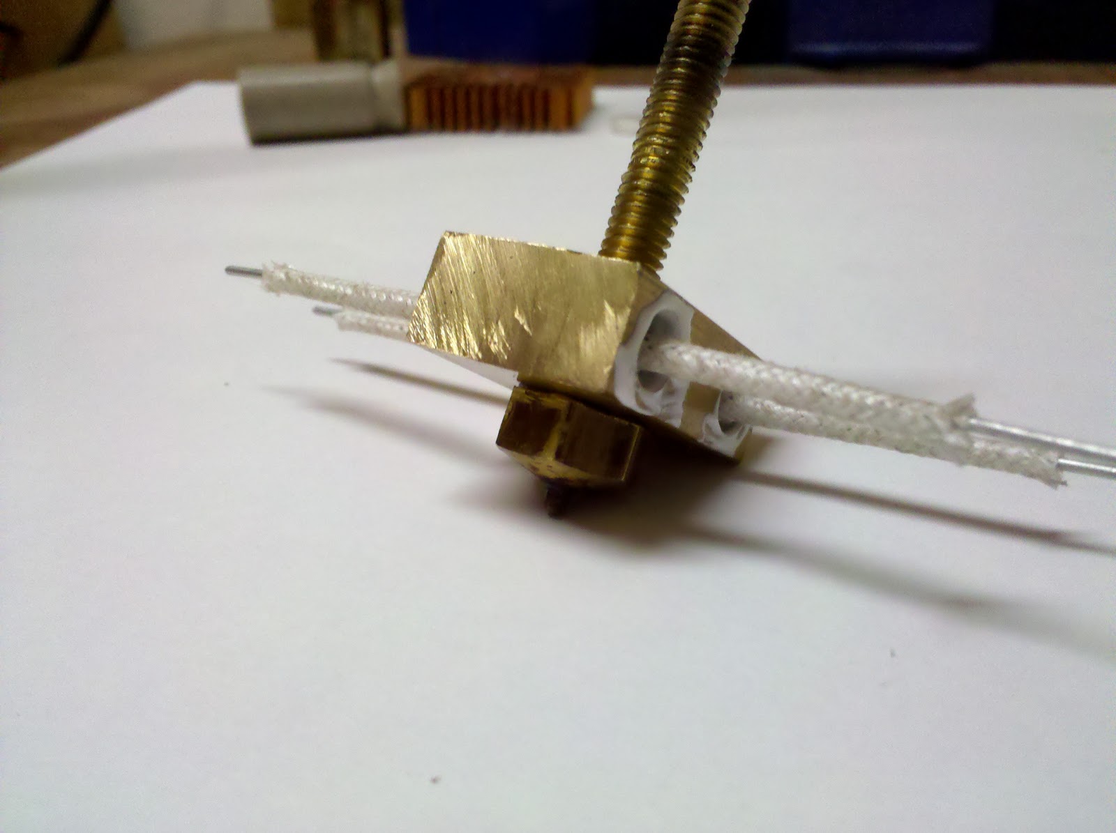
A drop of heatsink grease on the barrel improved thermal conduction from the block. I used fiberglass sleeving to insulate the resistor wires, though PTFE tubing or any high-temperature insulator works as an alternative.
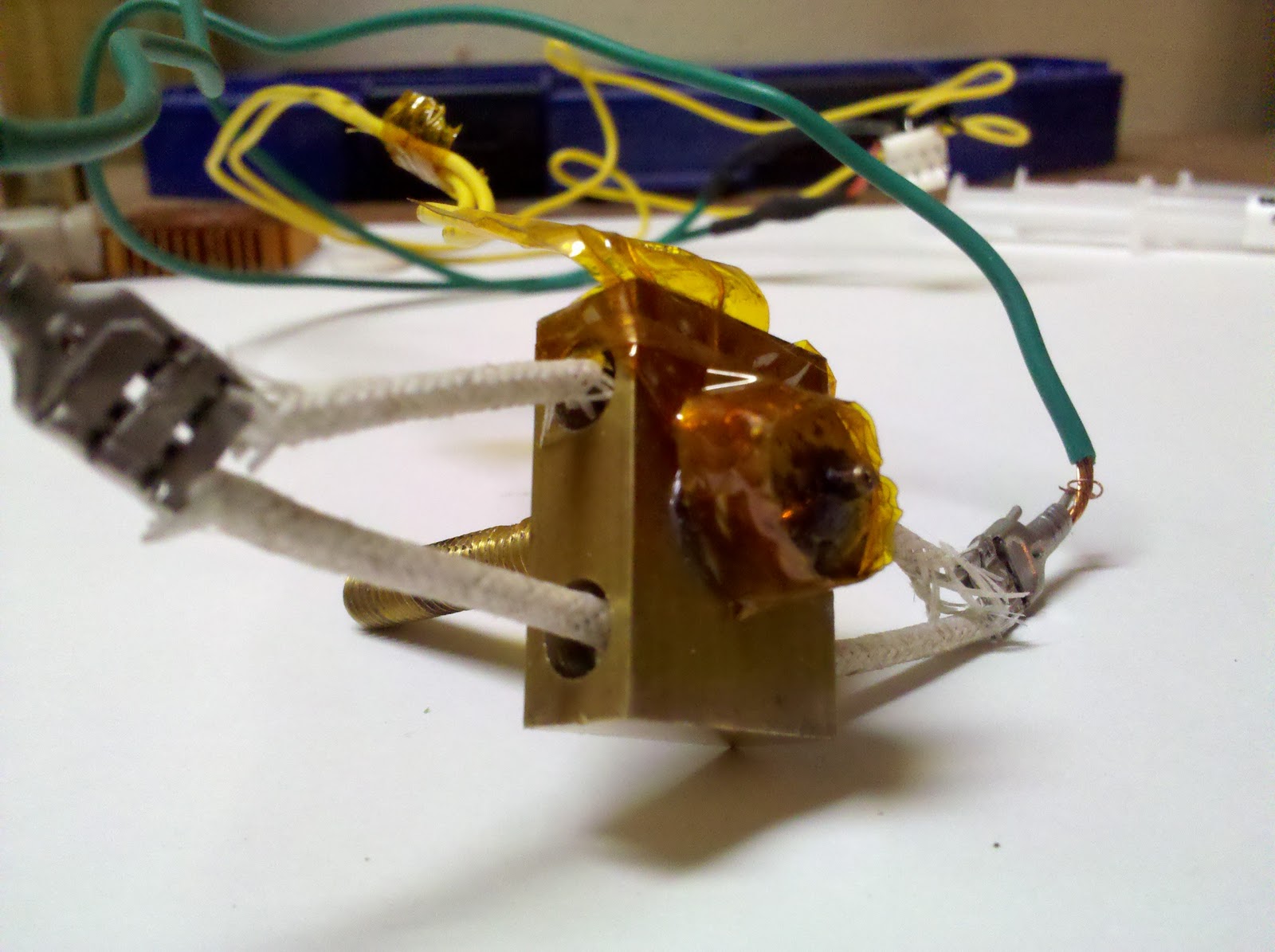
The thermistor attached directly to the nozzle, wrapped with Kapton tape for secure mounting and thermal coupling.
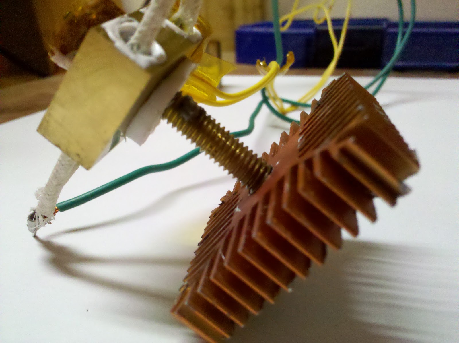
A PTFE washer provided thermal isolation between the hot barrel and the heatsink. Another drop of heatsink grease kept good thermal contact with the heatsink threads.
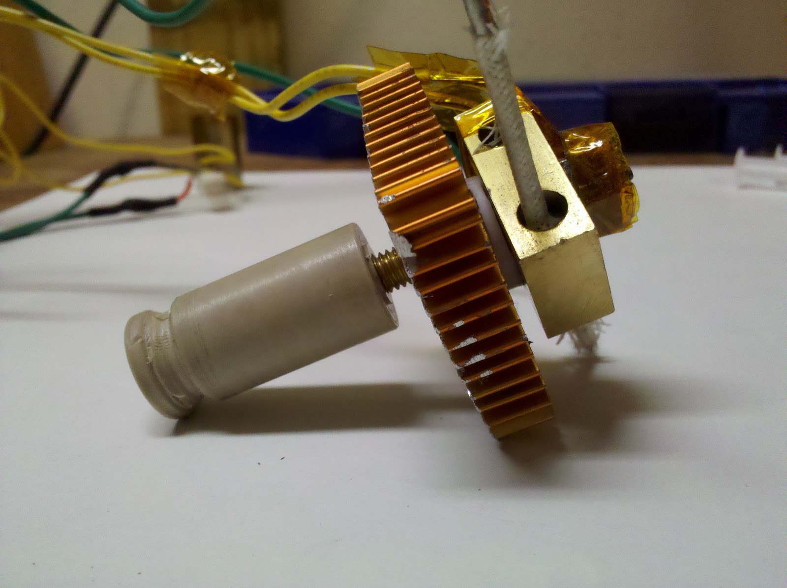
The complete assembly threaded into the thermal barrier and mounted back on the machine.
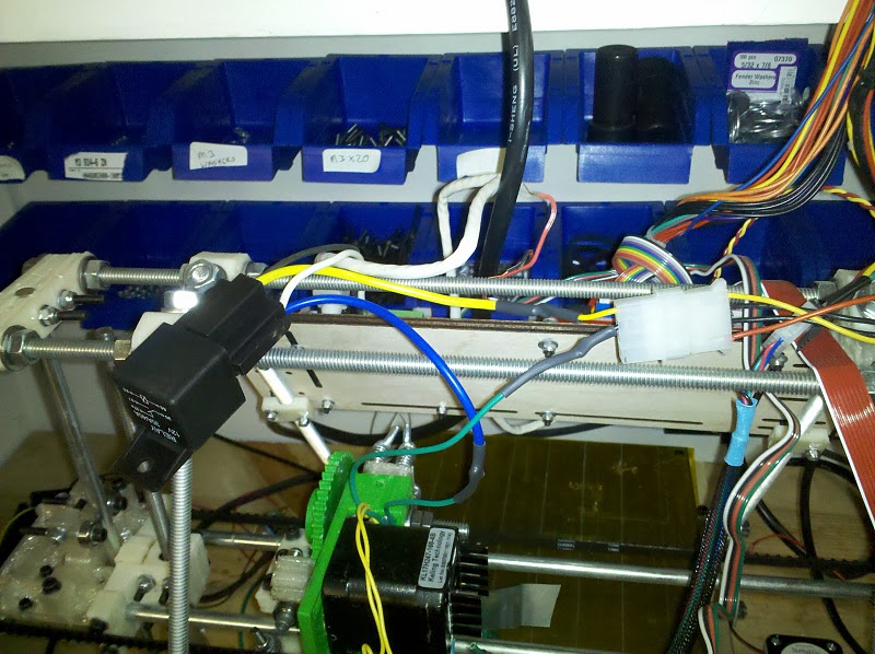
The two resistors in parallel created too much current draw for the extruder controller’s MOSFETs to handle safely. I added an automotive relay, with the extruder controller operating the relay coil and the relay switching the high-current resistor circuit.
Success! The double resistor heater provided consistent temperatures and rapid heat recovery, dramatically improving print quality and reliability. This setup finally delivered the performance needed to print Mendel parts consistently, bringing the project one step closer to a self-replicating machine.
Editor’s Note (2025): This article combines multiple posts from 2009-2010 documenting extruder development. The language has been updated for clarity, but the technical content accurately reflects the state of DIY 3D printing during this period. Modern hotends use cartridge heaters, much more reliable thermistors, and significantly better thermal break designs, yet the fundamental principles remain the same. The trial-and-error process described here was typical of early RepRap builders, each of whom had to solve similar problems with whatever materials they could find locally.